Autoship Hull Design & Surface Modelling
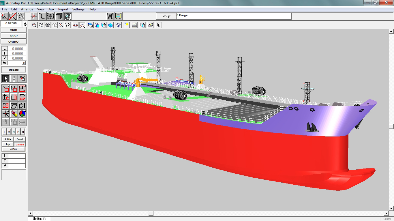
The Autoship hull design/surface modelling program combines the graphical user interface of Windows with the dexterity of NURBS (Non-Uniform Rational B-Spline) mathematics, the high-end CAD standard for surface modelling, to give you the tools to quickly and efficiently create any hull shape from a racing yacht to a super tanker, including the superstructure and appendages.
3D Viewing – The user-friendly interface enables the designer to work either in four views simultaneously (profile, plan, body and rotatable 3-D) or else one of the views singly by merely a click of a button. The four views may be dynamically resized at any time and may be individually zoomed and panned. There are ten levels of zoom/unzoom. Also featured are ten levels of undo/redo to trace and retrace design steps. You can specify multiple light sources and generate realistic, Z-buffered, smooth shaded, full colour renderings with walk through and printer-resolution export
Object Based Hierarchy – Autoship‘s building blocks consist of Points, Curves, Surfaces, Polyobjects and Groups. Groups are collections of objects, including other groups, which may be scaled, rotated, mirrored, offset, and instanced to allow very complex structures to be created from a minimal number of objects. Changes to an object are propagated through the groups that contain it. Autoship‘s Navigator window allows you to navigate through the model with minimal effort, control the attributes of the model’s objects and create and delete objects.
Objects – Points may be free in space or embedded on a curve or surface. Curves may be free, embedded on another curve or surface or projected onto a surface, and the curves ends may be attached to points. There are several methods available to create a curve, such as specifying endpoints, sketching, as arc or rectangle, by projection onto a surface, by lofting through points and by offset from an existing curve. Autoship also includes a library of NACA foil section curves. Surface edges may be attached to (or matched to) a curve or another surface. Several methods are available to create a surface, including specifying dimensions, rotating a curve about an axis, extruding a curve along a vector, sweeping pattern curves along one or two guide curves, ruling or developing between two curves, skinning through multiple curves and blending between two surfaces. During editing, the dynamic display feature allows you to see both the original and the edited version of curves and surfaces on the screen.
Feature Patches™ – A system for introducing local shape control on a surface without dealing with unwanted control points. The feature patch blends at its edges to the shape of the parent surface. When the parent surface shape is changed the patch moves with the change, retaining its own shape. Read more…
Edge Mate™ – Allows all or part of the edge of one surface to be matched exactly to all or part of another surface’s edge. The user can choose positional, tangent or curvature continuity from one surface to the other.
Project Integration and Export – Surfaces which incorporate Feature Patches and/or Edge Mate are fully integrated into the Autoship project. The surfaces are contoured, intersected, trimmed, meshed and rendered – just like any other Autoship surface. The surfaces export exactly via IGES, making transfer of designs from Autoship to other programs simple and accurate.
Scaling and Parametric Variation- An existing design can be changed to create a new design by application of piecewize lscaling or by varying specified parameter values. Both apply to single surfaces or groups. Longitudinal, transverse and vertical scaling can be specified separately and applied to the whole hull or a limited part of it. User-specified changes of parameter values (LCB, Cp, displacement, etc.) are achieved by an automatic iterative process.
Curvature Displays – To help in fairing, Autoship features many different types of curvature display. Curve surface and contour curvature may be displayed as porcupine quills in each view, or as a curve of curvature in a separate window. Additionally, surface curvature may be portrayed as a colour map of mean, Gaussian or absolute curvature, or as a coloured rendering with shading.
Engineering Accuracy – The user can specify a tolerance to be used for DXF output. Curves and surfaces are then automatically refined to meet or exceed that tolerance. The user can specify high accuracy for NC cutting or set a larger tolerance value to save on computation time. Models may be exported and imported in 2D or 3D via industry-standard DXF and IGES file formats. Autoship can also output a complete lines plan as a three-view, 2-D DXF as well as in tables.
Shell Expansion – A new algorithm results in much smoother and more accurate results; a new dialogue provides control of stations and output entities such as contours, layers, colours and even curves; a new Preview mode helps get to the desired final output faster.
Hydrostatics/Resistance – Autoship comes with built-in Quick Hydrostatics plus fast links to Autohydro for full hydrostatic analyses and to Autopower for resistance and powering prediction.
Operating System Requirements: Windows® 10 and 11 Professional (32 or 64 bit), .NET Framework 4.8 with a Pentium Processor. Minimum resolution: 1280 x 800 (WXGA). OpenGL: recommended v3.2 or higher, minimum v2.1.
|
||
Key Features
- Windows® 11 Compatible
- Metric or imperial units
- Choice of several main screen layouts
- 4 simultaneous views or single view
- Multiple Zoom and Pan
- US, European & customizable coordinates
- Ten levels of Undo and Redo
- OpenGL rendering with walk through
- Translucency in rendering
- Extensive use of context menus to speed operations
- Navigator pane provides tree-view control of model
- Export & Import DXF and IGES
- Edit planes: create a list of 3D views in which vertices are constrained to move only in the plane of that view
- Surfaces can be coloured, making it easy to pick out one surface in a complex design
- Developable surface generation plus the ability to export the flattened surface
- Curvature displays for curves and surfaces, including rendering of Gaussian and other curvatures
- Curve and surface knot redistribution
- Surface to surface intersection with trimming
- On-screen measurement tools
- Curve and surface fairing operations
- Extensive offset table generation
- Tools for matching existing hull forms
- Built-in foil shape library
- Quick hydrostatics, including sectional area curves
- Export geometry files to Autohydro
- Single button operation to create station contours from baseline data.
- Optional display compression in the X direction aids fairing
- Newly-enhanced Shell Expansion output
Pro Version
- Unlimited Max Length
- Unlimited Max # Surfaces
- Developable Surfaces
- IGES Import/Export
- Surface Match
- Feature Patch
- Edge Mate
- Viewer Walk Through
Standard Version
- Unlimited Max Length
- 40 Max # Surfaces
- Developable Surfaces