Autoload Offshore
Autoload® Offshore™ is the latest generation of our onboard stability and simulation software. Whether you have a semi-submersible, jack-up, drill ship, TLP, Spar, or other offshore vessel, Autoload Offshore will meet all your loading, stability monitoring and strength requirements. Configured specifically for each rig, platform, or vessel, Autoload‘s ability to simulate any current or anticipated loading condition will enable you to quickly verify stability, trim, drafts, and structural strength status.
As always with ASC systems, complete 3D models of the vessel (identical to the model used for creating the approved stability booklet) are used for all calculations. These models includes all buoyant parts, tanks, and void spaces. The non-buoyant superstructure is used for wind calculations.
Autoload Offshore’s interface is brand new and represents a complete departure from previous Autoload screen layouts. Autoload Version 6.0 was developed with Offshore customers very much in mind, and its design benefits from both discussion with Offshore industry representatives and the experience gained by thousands of users with versions 1 through 5.
The philosophy behind the new interface retains the priority ASC has always placed on current, immediate, intuitive and meaningful information; but the new interface also centres on these additional requirements:
- information most important to users must always be found in the same place, and cannot be hidden;
- easier and faster load handling and generation of related reports;
- improved simulation of both “what if” and real critical situations;
- critical loading condition, stability, and margins information must be available at all times.
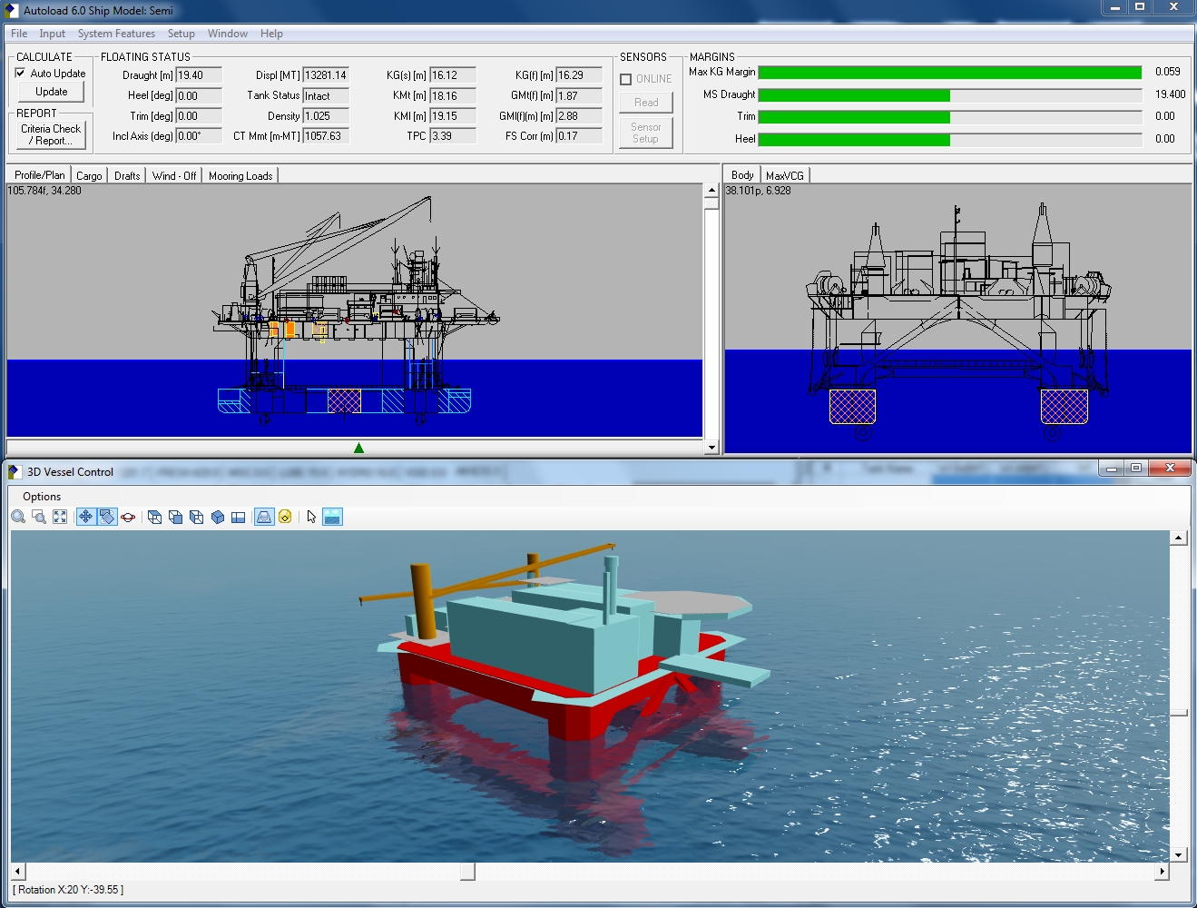
Autoload‘s User Interface
Autoload‘s User interface provides a complete picture of the current situation, by employing these main features:
• Upper screen area shows all important hydrostatic values and margins
• Middle screen area is used for graphical representation and editing of loads and floating position
• Lower area is for tabular weight editing
• Easy and fast load handling for generating the daily reports
• Simulation of any “what if”, or real, critical situations
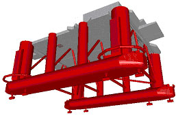
3D Vessel Model – used for all calculations
Key Interface Components
Managing Weights
Rig loads are in two main groups:
• Fixed Weights – the fixed weight dialogue allows input of all weights not carried by tanks
• Liquid (Tanks) Loads can be edited directly on the plan/profile/body images or in the tank dialogue. All tanks connected to sensors are updated at user-specified intervals. In the event of sensor failure, the user can designate the affected sensor(s) as offline.
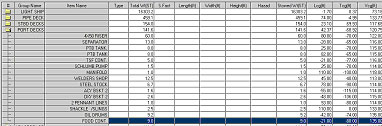
Fixed Weight Dialogue
Auto ballast function
Select four tanks and set target draft, trim and heel. Autoload searches for a solution.
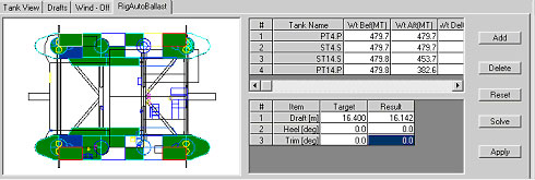
Auto Ballast Window
Anchor Chain Sensor Connection
Autoload can receive chain tension input from sensor interface connections.
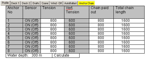
Window Layout
Draft Sensor System Interface
Adjust current loading condition to measured drafts by using the draft dialogue.
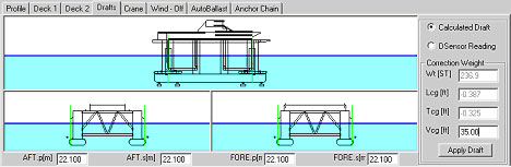
Draft Dialogue
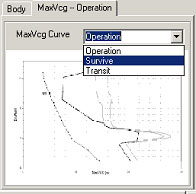
Max VCG
The max VCG Window indicates:
• All maxvcg curves; restricted area is shaded
• Current condition (current is selected)
• The ballast curve going through the condition